As a house resident I would like each room in the house to be at a comfortable temperature when I want to use it
To me the most important part of a smart home is the ability to keep rooms at the required temperature during the day. It’s all well and good having twinkly lights that go from orange to cerise because you have trained Alexa to respond to the dog barking but in my house heating is where the intelligence is needed. Our house has a traditional wet radiator system with a boiler and single room thermostat. I had a heating engineer commission the system when we moved in but it took him a long time to figure out the controls. My aim is to make a much more controllable system with simple wiring that anyone (including an electrician) could understand.
Stage 1: ZigBee Thermostatic Radiator Valves
Having dismissed all the “systems” available on the UK market as being knobbled in some way my research took me to AliExpress where ZigBee TRVs come in at only £20. I bought 10 of them and replaced the first set of old-fashioned Honeywell wax based TRVs with the new intelligent controllable devices. Fitting the new TRVs was a very simple process of unscrewing the old and fitting the new. They came with a variety of adaptors so I think there should be one to fit most radiators.
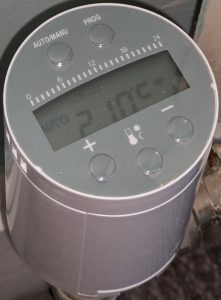
Tuya ZigBee Progammable TRV on AliExpress
They look quite smart and there is a (fairly limited) app that can be used to control them. They only have 4 temperature settings for the day but when you walk into a room and it is too cold it is a very simple job to turn them up using the app or the button on the TRV. There is some rudimentary automation available (such as geofencing) but overall they are light years ahead of the previous generation TRVs.
Tuya ZigBee Gateway
The Tuya ZigBee gateway is a bit of strange thing. It is a USB powered device that is needed if you want to communicate with the devices on the ZigBee network and use WiFi for management & configuration. For some reason it needs to communicate with China so the gateway lives on its own bit of network with access to the internet but nothing on my home WiFi. The Android app is where you set room temperatures up so an important part of the system. There is lots of information on the web about how to download/add/configure the app and TRVs and I don’t think I can add much to it. Adding devices to the app is also very simple.
Stage 2: Boiler Automation
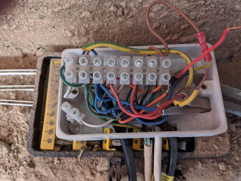
Central heating controllers are very simple state machines. Looking at the mess of cables above it is hard to see how simple and elegant heating control is and I needed to be very sure I knew what I was doing before getting my wire cutters out. No heating is not something that makes certain members of this household happy. My first step here was to replace the knot of cables above with a Honeywell 10-way Junction Box at Screwfix
**Disclaimer – All home wiring must be completed in accordance with building regulations. If you are not a competent person as defined in them then please seek a qualified electrician**
The flow for central heating is:
Timer turns heating on
If thermostat says temperature is too low then sends power on heating valve
If heating valve opens then turn on the boiler and pump. Some boilers will control the pump separately (so the pump is connected to the boiler and not the wiring circuit).
| Heating Programmer State | Heating Control Voltage Pin 4 | Thermo- stat State | Thermo- stat Output Voltage Pin 5 | Zone Valve State | Zone Valve Boiler Output Pin 10 | Zone Valve Pump Output Pin 10 |
|---|---|---|---|---|---|---|
| Off | 0 | N/A | 0 | N/A | 0 | 0 |
| On | 240 | Off | 0 | N/A | 0 | 0 |
| On | 240 | On | 240 | Open | 240 | 240 |
Domestic Hot Water (DHW) is very similar:
Timer turns DHW on
If cylinder stat says water tank temperature is too low then sends power on DHW valve
If DHW valve opens then turn on the boiler and pump. Some boilers will control the pump separately (so the pump is connected to the boiler and not the wiring circuit).
| DHW Programmer State | DHW Control Voltage Pin 6 | Thermo- stat State | Thermo- stat Output Voltage Pin 8 | Zone Valve State | Zone Valve Boiler Output Pin 10 | Zone Valve Pump Output Pin 10 |
|---|---|---|---|---|---|---|
| Off | 0 | N/A | 0 | N/A | 0 | 0 |
| On | 240 | Off | 0 | N/A | 0 | 0 |
| On | 240 | On | 240 | Open | 240 | 240 |
The most common wiring plan in the UK seems to be S Plan and should be connected up to a wiring centre using the standard pins below.
S Plan Wiring Pins
- Live
- Neutral
- Earth
- Programmer Heating Signal Feed Out/Room Stat Feed
- Room Stat Return/Zone Valve Feed
- Programmer DHW Signal Feed Out/Cylinder Stat Feed
- Unused
- Cylinder Stat Return/DHW Zone Valve Feed
- Unused
- Heating & DHW Zone Valve Return/Boiler Switched Live & Pump Feed
And here is the wiring diagram for this using two ZigBee relays as the central heating controller.
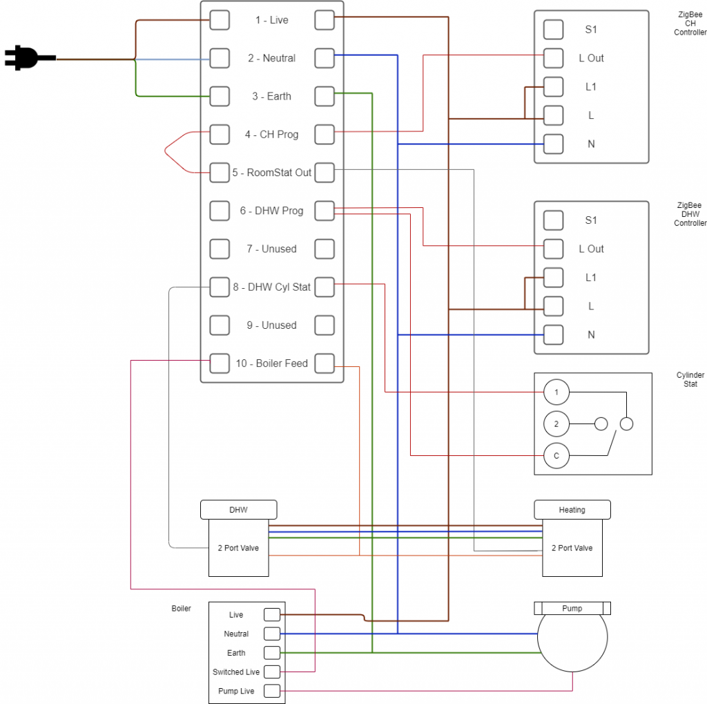
As stated above, your boiler may not have an output to control the pump. In that case the pump Live is connected to the Switched Live of the boiler.
Now I have the radiators deciding when they need to turn on and off independently I wanted to replace the Central Heating controller with a £10 ZigBee relay from AliExpress. Ultimately this is a very simple process. The relay output of the ZigBee relay for the central heating needs to feed pin 4. The room stat is no longer needed so jump across pin 4 & 5. For DHW connect the output of a second ZigBee relay to pin 6.
Tuya ZigBee Relay on AliExpress
I can also say to my phone “Hey Google, turn the heating on” and it turns on! 🙂